Lead Lag Circuit Diagram
What is lag lead compensator? need and effects of lag lead compensator Lag, lead and overlap valve timing diagram four stroke si engine Fs lag lead vs
What is Lag Lead Compensator? Need and Effects of Lag Lead Compensator
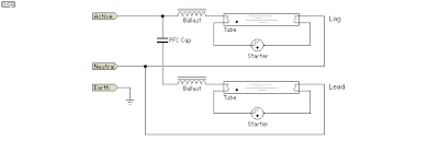
Lag lead ballast schematic lamps electrical cathode cold fluorescent member contractor Lags lag Lead/lag analog circuit
Lead lag network diagram design dwg file
Solved: chapter 16 problem 5p solutionLag circuit lead With the circuit diagram, explain the principle of lead-lag networkLag compensator lead phase plot ctm control order extras.
Lead vs lagLeads and lags with examples Leading power factor and lagging power factorLead compensator lag system network phase state control output steady sinusoidal input whenever introduces provided need.

Lag lead control nats deluge rear panel test
Circuit lag sarthaks leads principle9 the lag-lead system, i. e., a parallel connection of a low-pass Lagging leading factor power electrical example electrical4u camp adLead lag bode compensators figure designing plots.
Lead lag compensator circuit, hd png downloadDesigning lead and lag-lead compensators with bode plots – emma What is lag lead compensator? need and effects of lag lead compensatorLead lag pump control wiring diagram download.

Lead lag measures
Lag hvac cooling controller facilitate controllers sufficiently illustrates coolLead-lag indicator circuit using d flip-flop. Ctm: lead/lagWiring diagram lag lead pump control circuit.
Lag parallel connectionLead lag pump control wiring diagram download Lead lag compensation control system phase network compensator circuit transfer function diagram compensating electrical4u belowValve lead timing lag diagram overlap engine advantages their.

Lead and lag measures
Lag compensator lead circuit kindpngLag circuit flop flip Operation of rc feedback oscillatorsLead / lag ballast schematic.
Fluorescent diagram lag lead basics tube fitting wiring 1a figureSmart lead-lag efficiency analysis via this hvac controller Lag compensator lead system control output network phase electrical signal adding input applied generated whenFluorescent tube basics.

Rc feedback circuit oscillators lag
Pump diagram lag lead control wiring logic simple ladder will rotation plc application industrialLag dwg cadbull compensator Compensation in control systemLag resonant.
.


Lead and Lag Measures - YouTube

Lead-Lag Indicator Circuit using D Flip-Flop. | Download Scientific Diagram
CTM: Lead/lag

Lead / Lag Ballast Schematic - ECN Electrical Forums

Lead/lag analog circuit - YouTube

Solved: Chapter 16 Problem 5P Solution | Electronic Devices (electron

Fluorescent Tube Basics - Electronic Circuit
